
Precision Spur and Helical Gear Replacement Solutions
Replacement gear manufacturing for industrial gearboxes and equipment
When an existing precision spur or helical gear becomes worn, damaged, obsolete, or difficult to source, replacement requires more than duplicating its outside diameter and tooth count. The new gear must also correctly match the existing shaft, bore, keyway or spline, mating gear, center distance, bearings, and housing, while meeting the actual operating requirements for speed, torque, load, lubrication, and duty cycle.
Based in Taiwan, SC Gear specializes in medium- and large-size precision ground gears. Using original drawings, physical gear samples, or verified engineering data provided by the customer, we evaluate replacement gear manufacturing for industrial gearboxes and equipment, equipment retrofit, parts localization, gear reverse engineering, and custom OEM power transmission projects.
Replacement Gears Must Match the Complete Existing System
Replacing precision spur or helical gears in an industrial gearbox is not simply a matter of reproducing a gear with the same appearance. The engineering evaluation must also confirm:
- Tooth profile, lead, pitch, and runout
- Module or diametral pitch, tooth count, and pressure angle
- Helix angle, hand, and tooth thickness
- Center distance and backlash
- Bore, shaft, keyway, or spline fit
- Concentricity between the bore and gear teeth
- Material, surface and core hardness, and heat-treatment method
- Dimensional distortion after heat treatment
- Condition of mating gears, bearings, shafts, and housing
- Torque, speed, shock load, and duty cycle
- Lubrication, temperature, and actual operating environment
This type of evaluation is particularly suitable when:
- The original equipment manufacturer no longer supplies the part
- OEM lead time is too long or procurement cost is too high
- The original gear drawing has been lost or is incomplete
- Only a worn, damaged, or broken gear sample remains
- Equipment is being localized, upgraded, or retrofitted
- The new gear must reuse an existing shaft, bore, or mating gear
- The equipment has developed abnormal noise, vibration, pitting, wear, or tooth breakage
- A custom machine requires a newly developed gear transmission component
Replacement and Retrofit Projects We Can Evaluate
| Project Condition | Key Engineering Review |
|---|---|
| Original drawing available | Drawing review, tolerance confirmation, and verification of material and heat-treatment specifications. |
| No drawing, but a gear sample is available | Gear measurement, tooth-form analysis, geometry reconstruction, and reverse engineering. |
| Only field measurement data is available | Review of measurement references, methods, interface dimensions, and data completeness. |
| The old gear is worn or damaged | Assessment of the failure condition and the condition of mating gears, shafts, bearings, and housing. |
| The existing shaft or bore must be reused | Review of fit, tolerances, runout, keyways, splines, and assembly method. |
| A custom machine is being developed | Gear requirements evaluated according to load, speed, service life, and installation space. |
| OEM spare parts are obsolete or have long lead times | Alternative manufacturing and localization evaluated from samples or technical data. |
Building Manufacturable Specifications from Existing Gear Data
1. Project and Failure-Condition Review
The first step is to confirm the equipment application, reason for replacement, gearbox condition, available drawings, existing samples, speed, torque, duty cycle, lubrication method, and known failure symptoms.
If the original gear shows abnormal wear, pitting, spalling, cracks, or broken teeth, the mating gear, bearings, shaft, and housing should also be evaluated. This helps avoid replacing only one gear without addressing the actual cause of failure.
2. Gear Geometry Confirmation
Depending on the available project data, the items reviewed may include:
- Module or diametral pitch
- Tooth count
- Pressure angle
- Helix angle and hand
- Tooth profile and profile shift
- Face width
- Outside diameter, root diameter, and pitch-related dimensions
- Bore, shaft, keyway, or spline dimensions
- Center distance and mating-gear data
If the sample is already worn, the worn tooth form and dimensions cannot be treated directly as the original design values. They must be interpreted together with the mating gear, center distance, and operating requirements.
3. Shaft, Bore, and Assembly-Interface Review
Shaft and bore fit cannot be determined from a single measurement value. The following factors may affect the final machining specification:
- Bore roundness and possible ovality
- Localized wear on the shaft diameter
- Measurement position, direction, and datum
- Surface condition of the workpiece
- Measurement environment and workpiece temperature
- Concentricity between the bore and gear teeth
- Radial runout
- Press fit, shrink fit, or other assembly method
- Operating load and temperature
When the replacement gear must be installed on an existing shaft or assembly, the interface dimensions, fit tolerances, and assembly requirements should be confirmed before production machining begins.
4. Material and Heat-Treatment Review
Material and heat-treatment selection should be evaluated according to:
- Tooth-surface contact load
- Tooth-root bending load
- Shock or reversing load
- Wear-resistance requirements
- Surface and core hardness
- Gear size and structure
- Expected service life
- Actual operating environment
Common reference materials include S45C, SCM415, SCM420, SCM435, SCM440, SNCM220, SNCM439, and 17CrNiMo6. Depending on the material and application, SC Gear primarily evaluates carburizing, quench-and-temper treatment, or induction hardening. Final material, hardness, and heat-treatment specifications are confirmed for each project.
5. Gear Grinding and Quality Inspection
After heat treatment and finish machining, tooth grinding and inspection are performed according to the approved drawing and agreed accuracy requirements.
Inspection items may include:
- Tooth-profile deviation
- Lead or helix deviation
- Pitch deviation
- Radial runout
- Runout and concentricity
- Bore and assembly dimensions
- Tooth-contact inspection
- Surface and core hardness
- Dynamic balancing
- Other project-specific dimensions and quality records
6. Delivery and Assembly Support
Inspection documents, material certificates, hardness records, packaging, assembly notes, and the scope of technical support are confirmed according to the project, delivery destination, and customer requirements.
A single gear normally cannot undergo no-load running, vibration, noise, or temperature-rise testing as a complete-machine verification. If the customer provides a complete gearbox, tooth contact, backlash, no-load running, and related functional checks may be evaluated according to the project scope.
Reverse Engineering Service Scope
SC Gear provides reverse engineering services for medium- and large-size gears. After receiving a physical sample, our engineering team can perform measurement, analysis, and manufacturing evaluation in a controlled in-house environment.
Gear Design Reconstruction
Dimensional measurement, tooth-form analysis, and reverse modeling are performed to establish complete engineering drawings and manufacturing data.
Material Analysis
The material specification and properties are identified as a basis for manufacturing, heat treatment, and quality control. Third-party material testing can be arranged when required.
Hardness Inspection
Surface and core hardness are measured and confirmed as references for heat-treatment selection and replacement specifications.
Failure Analysis
Wear, tooth breakage, fatigue, pitting, cracks, and other failure conditions are reviewed to help identify possible causes and improvement directions.
Mating Gear Verification
The meshing relationship, geometry, center distance, and contact condition of the mating gear are reviewed as important inputs for repair, remanufacturing, or new production.
Based on the analysis, SC Gear can evaluate reverse manufacturing, gear repair, custom manufacturing, and OEM spare-part replacement solutions to help reduce downtime, shorten spare-part waiting time, and improve equipment reliability.
SC Gear currently does not provide customer-site or overseas field measurement services. Precision gear reverse engineering requires professional in-house measuring equipment and a controlled environment, so customers are normally asked to send the sample to our facility for measurement, analysis, and inspection.
Sample Submission and In-House Measurement Process
SC Gear currently does not provide customer-site or overseas field measurement services. Precision gear reverse engineering requires professional in-house measuring equipment and a controlled measurement environment to verify gear dimensions, tooth profile, lead, hardness, assembly interfaces, and related geometric conditions.
Customers may first provide overall gear photos, images of damaged areas, equipment information, and any available drawings. SC Gear will conduct an initial review and identify the sample and technical information required. When further reverse engineering is necessary, the gear sample should be sent to our facility for measurement, analysis, inspection, and manufacturing evaluation.
Precision Spur and Helical Gear Manufacturing Capability
| Capability Item | SC Gear Capability |
|---|---|
| Ground gear accuracy | DIN 6 / JIS 2 can generally be evaluated. DIN 5 / JIS 1 to DIN 4 / JIS 0 may be evaluated for high-speed, low-noise, or high-precision projects depending on workpiece conditions. |
| External gear capacity | Overall machining capability up to Ø3,200 mm outside diameter. |
| Module range | Overall capability from Module 1 to 50. |
| Helical gear specifications | Equipment capability may cover helix angles from 2° to 45°. Actual machinability depends on diameter, module, face width, tooth count, and interference conditions. |
| Materials | Carbon steels or alloy steels selected according to load, wear resistance, and operating conditions. |
| Heat treatment | Carburizing, quench-and-temper treatment, or induction hardening evaluated according to material and application. |
| Replacement gear projects | Evaluated from approved drawings, customer samples, or verified engineering data. |
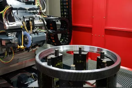
| Gear grinding | Performed with KLINGELNBERG-HÖFLER and GLEASON-PFAUTER gear grinding equipment. |
| Quality inspection | Tooth profile, lead, pitch, runout, dimensions, and hardness inspected according to agreed requirements. |
Capability note: The maximum outside diameter of Ø3,200 mm, Module 1–50, and the highest accuracy of DIN 4 / JIS 0 represent different overall capability ranges under different conditions. They do not mean that one gear can simultaneously meet all maximum limits. Actual manufacturability depends on gear size, module, face width, helix angle, material, heat treatment, structure, and inspection requirements.
Main Gear Grinding Equipment
| Equipment | Quantity | Primary Capacity |
|---|---|---|
| KLINGELNBERG-HÖFLER RAPID 800L | 2 | Maximum outside diameter Ø800 mm; capable of grinding external and internal gears for medium- and small-size high-precision applications. |
| KLINGELNBERG-HÖFLER RAPID 2000 | 1 | Maximum outside diameter Ø2,000 mm; capable of grinding external and internal gears for medium- and large-size precision applications. |
| KLINGELNBERG-HÖFLER RAPID 3000L | 1 | Maximum outside diameter up to Ø3,200 mm; capable of grinding external and internal gears, mainly for large precision gears. |
| GLEASON-PFAUTER P2000/2400G | 1 | Maximum outside diameter Ø2,400 mm; capable of grinding external and internal gears, mainly for large precision gears. |
Actual outside diameter, inside diameter, module, face width, helix angle, and achievable accuracy are evaluated according to the drawing and equipment conditions.
Quality Inspection and Available Documentation
SC Gear can provide relevant quality inspections and documents according to product specifications, customer technical requirements, procurement standards, and contract terms.
- Material Certificate / Material Test Certificate
- Heat Treatment Report
- Hardness Inspection Report
- Non-Destructive Testing Report (UT / MT / PT)
- Gear Inspection Report
- Dimensional Inspection Report
- Runout & Concentricity Inspection Report
- Dynamic Balancing Report
The actual inspection scope, record format, and documents provided are confirmed according to the product specification, customer requirements, and order terms.
Typical Applications
SC Gear custom spur and helical gears can be evaluated for applications including:
- Replacement gears for industrial gearboxes and equipment and parts localization
- Machine-tool transmission systems
- High-speed gearboxes
- Steel and heavy industrial machinery
- Petrochemical and process equipment
- Cement industry equipment
- Printing and packaging machinery
- Custom machinery and OEM power-transmission systems
- Gearbox repair, retrofit, and performance upgrades
Other applications such as mining, marine equipment, wind power, robotics, and automation systems can be evaluated according to product specifications, operating conditions, and project requirements.
What Information Is Needed for a Spur or Helical Gear Replacement RFQ?
Existing Technical Data
- Original gear drawing, gearbox drawing, or physical gear sample
- Overall gear photographs and close-up photographs of damaged areas
- Module or DP
- Tooth count
- Pressure angle
- Helix angle and hand
- Face width
- Bore, shaft, keyway, or spline dimensions
- Mating gear data
- Center distance
Material and Quality Requirements
- Material specification
- Heat-treatment requirements
- Surface and core hardness
- Gear accuracy standard
- Inspection-report requirements
- Material-certificate requirements
Operating Conditions
- Input and output speed
- Torque or transmitted power
- Duty cycle
- Shock or reversing load
- Lubrication method
- Operating temperature
- Existing noise, vibration, wear, or failure symptoms
Commercial Information
- Required quantity
- Target delivery date
- Destination country
- Prototype or long-term demand
- Packaging and documentation requirements
RFQ Process and Delivery Information
| Item | Description |
|---|---|
| RFQ | The customer provides drawings, samples, or technical requirements for manufacturability and technical-feasibility evaluation. |
| RFQ evaluation time | Standard cases generally require approximately 3–7 working days for technical evaluation and quotation. Special specifications, reverse engineering, or projects requiring further analysis are confirmed separately. |
| Prototype and order quantity | Single-piece prototypes, small-batch production, and volume production can be supported. Actual acceptance conditions depend on the product specification and project scope. |
| Lead time | Standard projects generally require approximately 60–120 calendar days. Actual lead time depends on size, material availability, heat treatment, machining processes, inspection requirements, and production capacity. |
| International delivery | EXW, FOB, and other agreed Incoterms® can be supported according to customer requirements. |
Frequently Asked Questions
Can a replacement gear be manufactured without the original drawing?
A project can begin with a physical gear sample. However, before the final manufacturing specification is established, the gear geometry, material, hardness, wear condition, mating components, and actual operating conditions must still be confirmed. If the sample is severely worn, the worn dimensions cannot be treated directly as the original design dimensions.
Can every gear be made to DIN 4 or JIS 0?
No. A single maximum accuracy grade cannot be applied to every gear. Achievable accuracy depends on gear diameter, module, face width, geometry, material, heat treatment, wall thickness, and inspection conditions. SC Gear’s highest published ground-gear capability can reach DIN 4 / JIS 0, but every project must be evaluated individually.
Is a 2°–45° helix angle available for every helical gear?
Not necessarily. The 2°–45° range represents equipment capability. Actual machinability depends on gear size, module, face width, tooth count, product structure, and interference conditions.
How are shaft and bore fit tolerances determined?
They must be determined from confirmed shaft and bore dimensions, the tolerance system, surface condition, operating temperature, assembly method, load, and runout requirements. A single field measurement is not sufficient.
Can SC Gear perform gear measurement at the customer’s site?
SC Gear currently does not provide customer-site or overseas field measurement. Precision gear reverse engineering requires professional in-house measuring equipment and a controlled environment, so customers are normally asked to send the sample to our facility for analysis.
What materials are available for custom gears?
Common materials include S45C, SCM-series steels, SNCM-series steels, and other alloy steels. Final material and heat-treatment selection depends on load, wear, shock, hardness, gear size, and operating environment.
Can a single gear undergo running and noise testing?
A single gear is not yet installed in a complete transmission system, so no-load running, vibration, noise, and temperature-rise tests generally cannot be performed on the gear alone. Dimensional inspection, gear-accuracy inspection, tooth-contact inspection, runout, concentricity, hardness, and dynamic balancing can still be performed as required. If a complete gearbox is provided, related functional verification can be evaluated according to the project scope.
Need to Replace a Worn, Obsolete, or Undocumented Industrial Gear?
If an existing spur gear, helical gear, or gearbox component has suffered wear, tooth breakage, or other damage, or if replacement parts are difficult to obtain because of discontinued production or long overseas lead times, SC Gear can evaluate gear repair, reverse engineering, and custom manufacturing solutions based on the available drawings, samples, and operating conditions.
Please provide available gear drawings or sample photos, module, number of teeth, helix angle, bore and keyway dimensions, mating gear information, as well as operating speed, torque, load, lubrication method, and known failure conditions. Our engineering team will review the available information, identify any additional technical data required, and evaluate the appropriate material, heat treatment, manufacturing accuracy, inspection requirements, and delivery approach.
- Equipment
 Gear grinding machine for both external and internal gears, suitable for small- to medium-sized high-precision gears
 Maximum machining diameter: Ø800 mm
 Maximum machining diameter: Ø2,000 mm; capable of grinding both external and internal gears, suitable for medium- to large-sized precision gears
 Maximum machining diameter up to Ø3,200 mm; capable of grinding both external and internal gears, primarily used for large precision gears
 Maximum machining diameter: Ø2,400 mm; capable of grinding both external and internal gears, primarily used for large precision gears
- Related Product
Custom Gears
Shiuh Cheng Gear specializes in OEM customized gear manufacturing. Whether you need to develop proto-type, or need professional knowledge assistance, our gear...
Details